
I ordered the after market Rear Mount Gas Tank Kit from LMC Truck. You can see the details in the image below. For this truck, I found that I needed the following parts in the diagram: 1, 2, 7, 8, 11, 12, 13(x2), & 14. In kit #1 I did not need the straps provided and I ordered 2 sets of #13 because I wanted to be sure to secure my fuel line so it did not rattle or rub at all. LMC does not provide any instructions on mounting this tank so I had to figure it all out on my own.

After I dry fit the tank, I found that the rear most frame cross member needed to be cut out and moved back. I torched the rivets off, cleaned up the mess and re-primed and painted the damaged area... I should have done this before I painted, oh well.


You can see that it just fits in the opening. I set it about 1/4" away from the front cross member shown below. (*Note: The 1/4" space was on the drivers side only. I later found that the tank is not square. In the finished product, the passenger side of the tank is quite a bit further from the cross member and not shown in the photo below).
There was a little over 1/8" on each side. Right away I realize that the tank was sitting too high in the frame. If I mounted it directly as shown, the neck would extend about 5 inches higher than the inside of the truck bed. That will not work!

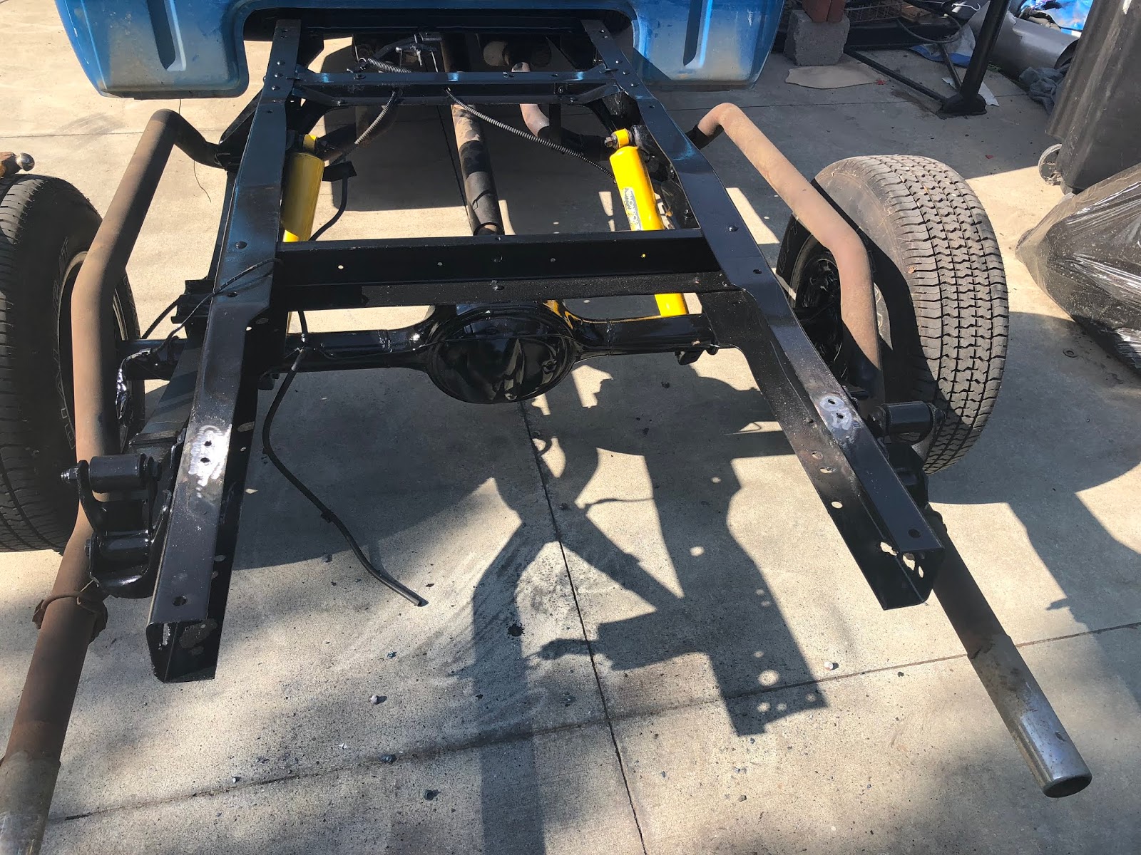
I went and measured the bed rails where the rear most and bed bolts mount to the frame. Also the second from the rear most rail. The rear most rail was 1 1/2" from frame to the bottom of the bed and the next rail was 1 1/8". This is the distance from the top of the frame to the bottom of the underside of the bed. I then cut some PVC pipe to use to help visualize where the bottom of the bed will sit.

Using a 2x4, I could now even better visualize and measure the space.

Way too high!

As shown below, the bottom of the bed would be 2" from the top of the tank. The ripples in the inside of the bed are about 3/8" tall. So adding 3/8", the inside of the bed would be at 2 3/8" from the top of the tank. This would put the top of the filler inlet at nearly 5 1/4". This will not do! I need to drop the tank.

After dropping the tank the 3" that I estimate is needed, I found that the tank only 12" from the floor. I did not want it that low, so I made a plan to cut both the filler neck and the neck coming from the tank.
Using a large pipe cutter I was able to carefully cut off a little over 1" of the tank neck. I was very careful no to knock any crud inside the tank.


On the filler neck, I was able to trim of about 1/14". I suggest that you save this piece that you cut out. I used it later when I made the jig to cut the hole in the bed floor...

After removing the retainer chain, I used a vice and hack saw to cut down the filler neck. I then drilled an counter sunk a new hole for the retainer chain (the chain that connects the cap to the neck).

After dry fitting the tank again I found that I now have 15" clearance from the bottom of the tank to the floor. This left me a 1 1/4" gap between the tank mount and the truck frame. This was easily fixed with a couple pieces of 1 1/4" square tubing. I cut the tubing at 13" long and drilled two holes, one at 3" and another at 10".


As you can see below, the truck frame is slightly indented. This caused a new problem. The bolts will mount to the frame in the front (toward the cab) just fine but the rear mounts are missing the frame by about 3/4". I will now manufacture some angled brackets that I will attach to the square tubing.


And here they are. The left, or drivers side bracket has a lip that is 3 1/4" and the right side is 2 1/2". Notice that I left a gap between the lip and the top of the square tubing so that the truck frame can slip between them (scroll down a bit to see what I mean).


May 21, 2018
Paint is dry. I now mount the brackets to the tank. I just did the rear most holes. I used blue lock-tight on all bolts during the tank mounting.


Next I put the fuel tank back in the frame and mounted the front most bolts.

You can see I miss measured the hole in the frame on the right front hole. I had all four bolts in the holes when I dry fit it, so I am not sure why this happen.

So far so good. You can see below how the lips that i welded on the brackets sit on the frame.


I didn't take photos, but as you can see in the photo above, the lip is just sitting on the frame. I used a pair of vice grips to pull that lip down flush to the frame, drilled a 3/8" hole trough the frame and lip and attached it securely with a 1" bolt.
Time to put the frame cross member back in. I want to use the holes in the cross member and just drill new holes int he frame. I measured the holes.

Below you can see that I am putting the cross member back in the frame up side down. This is to allow room to service the rubber hose on the fuel filler neck after the bed is put back on. This up side down (and backwards) placement gives me an extra 4" of work space!

I used the old frame holes to get the cross member aligned evenly. As you can see below, the edge of the cross member is covering exactly half of the rear most old hole. Same on both sides.

With painters tape, I measured from that half way point on the old hole at 1" and 2 1/8".

I then drilled through the top, aligned the bit to the holes in the bottom of the cross member and continued drilling the rest of the way through the bottom of the frame.


All holes drilled, time for bolts.

Bolts in, again with blue lock-tight.


15". It is sitting perfect (in my opinion).

May 22, 2018
Here is the sending unit that came with the kit. I am going to test it before installing it though!

On the bench, Ohms meter attached. I get readings throughout the entire range of the float arm... so I think we are good to go!


Rubber ring goes on the sender...

Sender goes in the hole...

Sender sits in the hole...

Retainer ring gets started. It aligns to all three notches and before I started tapping it into place I was able to get each tab started just barely...

See, each tab just barely started... this is about all I could do by hand, but it's enough.

Next I tapped it into place slowly with a small ball peen hammer and a very dull chisel. I made sure the chisel was very dull so that I did not cut the metal. I turns about 1 1/2" before the tabs are fully locked.

The roller valve acts as a vent so when the fuel level starts to drop the tank will not implode on itself. Easy install.

The fuel line that came from LMC is very playable. It is very easy to work with and I did not need any bending tools.

I bought some extra 3/8" fuel line to use in areas where the fuel line may rub against the frame.

Using a flaring tool, I put a flare on on the tank end of the line.

Here you can see the fuel line is dry set with its first bend.

First mount in place...

Now the fuel hose attaches the fuel line to the sender tube. You can see I put a piece of extra hose just in case the line rubs against the top of the tank.

Fuel line all in place and mounted down. The black areas that you see, and the black area where the line crosses over the top of the frame, are all the extra fuel hose. These are places where the line would be rubbing against the frame or rivets on the frame.


Time to ground the sending unit...

I used a rat-tail file to remove the paint and get the frame to bare metal providing a good ground.

Here is the finished ground. I will be painting this area later to seal it from rust.

I added a couple feet of 1/4" fuel line to the roll over valve. I rolled up and folded over a piece of stainless steal mesh attached with a hose clamp to this hose. This is to prevent bugs (we have these wasps that collect mud and fill small holes like this).

I manipulated this vent hose to face the rear of the truck and attached it to the frame.


As you can see below, I used a large piece of sturdy card board to create a jig for cutting the hole in the bed floor. I pushed three of the bed bolts through the card board into the frame holes that these bolts correspond to. I made sure there was no sagging in the card board. I then cut the card board away until it was about 1" from the neck hole on the tank.

Below you can see how I placed the piece of the filler neck that I cut away earlier. I placed it centered on top of the tack neck plug and pressed firmly on the card board. This created an impression on the card board.


I removed the screw and then flipped the card board over again and took the jig to my bed. I put the three screws in the bed. With a hammer, I pounded the screw to make an impression on the bed floor.

I then removed the jig and used a center punch to pound a good impression in the bed floor. This will give me a good start for the hole saw. You cannot see the impression, but you can see where I marked it with an X. Note how the X is not center on the rail. The filler neck is about 1 3/4" across. If I was to cut a hole that was 1 3/4", I really do not have good way to seal the neck from water and junk getting on top of the tank. I decided that I was going to over size the hole and further customize the area.

I chose to cut a 3" hole in the bed and will further customize this hole with a 4" plate. It is hard to describe what I have in mind, but I will go into full detail later in this post.

The bed went back on very easily with the tractor and fork attachment.

I jig was spot on. The hole is perfectly centered tot he filler neck on the tank.

I fabricated a platform for the gas filler neck to sit in. This will also serve to water proof the whole so that any water from the bad cannot leak onto the top of the tank. I forgot to take photos of the construction, but basically I cut a donut with the inner hole to match the size of the filler neck and the outer edge just larger than the hole in the bed. Here is the final product.


I ground down the bed to prep it for installation and welding.

Here are some pics of it before welding. You can see that the hole for the tank is not centered to the bed rail, this part will help to make the cap look "right" in the bed.


Here is is after the welding is done. I will grind it down better and use some filler to clean it up and smooth it out.


I finally had a break in the weather and was able to get my spray in bed liner done. I also installed the filler neck hose and the gas cap. With this post, I am finally done with the piece!


No comments:
Post a Comment